Step1:Locating a Power Source and Building a Hardwire Power Connector
While we had our gloveboxes removed to install UNGO security alarms, Rachel and I decided to hardwire our V1 radar detectors. I also wanted to hardwire my Garmin Color Street Pilot GPS.
The first step was locating a power source.
MZ3net offers several articles on hardwiring radar detectors. Vince Parson's excellent tome on tapping power from the cellphone power connector in the center console provides the basic information for building a mating connector to provide ground, 12volts of switched power for the V1 and 12volts of unswitched power for my GPS.
When connected to switched power, a device will have power only when the ignition switch is turned on. When connected to unswitched power, a device will have power as long as the car battery is alive and connected.
To briefly summarize the key points in Vince's article: Buried somewhere inside the center console, near the parking brake, is an 8 pin connector intended to provide power for the BMW mobile phone. The connector provides both switched and unswitched power sources. The parts to build a mating connector are difficult to purchase but engineering samples may be obtained from AMP Electronics. Contact information is in the final section. The connector and pins arrived within a week.
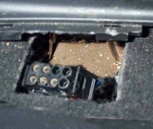
Locating the BMW cellphone connector may be a challenge. Pull up the shift boot. You may also wish to remove the rubber insert. Pull up the parking brake boot cover and look for a rectangular panel cut into the foam padding. Remove this panel and feel around under the padding. After several attempts, I found the power connector and was able to pull it towards the cutout. Here is a photo of the connector. Click for a larger image
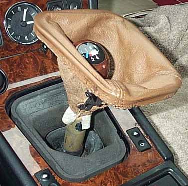
This procedure did not work for Rachel. We were able to locate her power connector by searching at the rear of the shift boot, in the area below the emergency flasher button.
There was some concern the wiring was different on models after 97 so I used a volt meter to verify that Pin #1 was 12volts unswitched, pin #2 was ground and pin #5 was 12volts switched.
With power source located, it was time to build the mating connector.
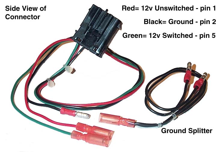
To build a connector that provides Ground, 12volt Switched power and 12volt Unswitched power you will need 18 gauge stranded wire in three colors, wire strippers, crimpers and snap connectors (Radio Shack part #64-3085) in addition to the parts from AMP.
- Cut three 24-inch lengths of different colored wire. We used Red, Green and Black. Strip the ends.
- Crimp one of the 0.098 inch pins from AMP onto one end of each of the wires.
- Push the pins into the back of the male connector from AMP. They will "snap" into place in a rather permanent fashion. Red wire into Pin hole #1, Black wire into Pin hole #2, Green wire into Pin hole #5. The connector has tiny numbers stamped next to the holes.
- Crimp a male snap connector onto the bare end of the black wire.
- Crimp a female snap connector onto the bare end of the red wire.
- Crimp a female snap connector onto the bare end of the green wire.
To build a splitter for the ground cable:
- Cut two 6-inch lengths of black wire.
- Strip the ends and crimp a male snap connector on one end of each wire
- Twist the bare ends of the wires together so they can fit into a snap connector and then crimp a single female snap connector onto this twist.
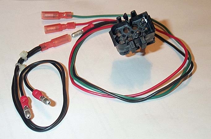
What we have now is a male mating connector and a splitter for the ground wire
In this arrangement the connector is constructed with:
Pin #1 Red is unswitched 12volts - always hot. Female snap connector. Power for GPS.Pin #5 Green is switched 12 volts - hot only when ignition is on. Female snap connector. Power for V1.
Pin #2 Black is ground. Male snap connector. Splitter provides ground for both GPS and V1.
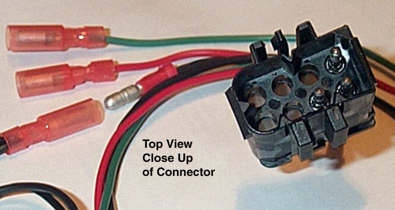
Here is a side view of the connector and splitter. And a top view and a closeup of the inside of the male connector.
The 2-foot wires allow the power connections to be brought up into a more accessible area in front of the shift boot, below the HVAC controls. Wishing for Rachel's small hands, I pushed the wires into the padding cutout, toward the passenger side of the console and somehow managed to feed them along the passenger side of the shift boot.
Push the male snap connector on the Ground cable into the female snap connector on the Ground splitter.
Verify that none of the snap connectors are touching metal and plug the mating connector into the cellphone power connector. If you have an automotive voltage tester with a 12v bulb, verify the power and ground cables. The connector is now ready to provide power. You can temporarily keep the cables at the base of the shifter, out of the way while running other cables.
On to Hardwiring the V1...